| Català | Castellano | English |
|
||||||
| JOptics Course | ||||||
|
||||||||||||||||||||||||||
|
Light polarization and Fresnel laws In this applet we study polarization of light and its reflection and refraction in isotropic media. The first window shows how to achieve the different polarization states of light by superposing two plane waves with special characteristics. The second and third windows show the behavior of reflected and refracted waves depending on the properties of an incident wave on a surface separating two media. The first medium is a dielectric while the second one can be either a dielectric or a conductor. Both the amplitude ratios (Fresnel coefficients) and the polarization ellipse changes are studied. "Polarization" window In this window we study the superposition of two plane waves of the same frequency, traveling in the same direction and that have perpendicular electric field directions, different amplitudes and with a phase delay between them. The amplitudes of the p (Ap) wave and the s (As) wave and the phase delay δ between them can be changed with the sliders. The plot at the bottom represents these two waves. The corresponding electric fields Ep and Es can be expressed as: As the waves propagate, the endpoint of the resultant electric field vector traces an ellipse, which is plotted on the upper left graph. We can also see the characteristics of this polarization ellipse: the semimajor and semiminor axes, and the angle with the p-axis, in degrees. The Stokes vector S describing the polarization state of light is indicated as well. The Stokes parameters are computed in the following way: The sign of the S parameter shows whether light is right-handed (S>0), in other words it turns clockwise, or left-handed (S<0), when it turns counter-clockwise. This is indicated in the black window by the letter R or L, respectively. "Dielectrics" window In this window we study light reflection and refraction in dielectric isotropic media, taking into account Fresnel equations. These equations specify the values of the electric field vector amplitude when light changes from one medium to another one, or when it is reflected, as a function of the incident amplitude. We suppose that we are working at a frequency (wavelength) range for which the media are non-absorbent. Let us consider an incident wave on a surface separating two transparent media with indices of refraction n and n'. If the incident angle is φ, the wave is reflected with a reflection angle equal to the incident one and is transmitted to the second medium with a refraction angle φ' that can be calculated as: The indices of refraction of the two media and the incident angle can be changed with the sliders. The program calculates the refraction angle and plots the incident (red), reflected (green) and refracted (blue) rays making the corresponding angles with the surface normal. It also computes the Fresnel coefficients, which are the ratios of the reflected (A'') or refracted (A') amplitudes to the incident amplitude (A): The p and s subscripts refer to the field that vibrates parallel (p) or perpendicularly (s) to the plane of incidence. This plane is determined by the incident ray and the surface normal (on the plot it corresponds to the plane of the screen itself). The p component is represented as a vector with different orientations on this plane, while the s component is plotted as a vector pointing towards the inside or outside of the plane of the screen. For normal incidence, the formulae become: When the "Fresnel coefficients" button is pressed (default option active when starting the program) we can see a plot of the Fresnel coefficients variation with the angle of incidence, in different colors. A yellow dot over the graph indicates the selected incident angle. There are some particularly interesting cases:
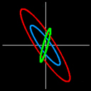
This angle is shown on the plot. In this case, we have: Both reflection coefficients have modulus 1 and there is only a phase delay 2(β-α)-π between the two components (the angle π refers to the minus sign in rp), with where Pressing the "Polarization" button opens a new window. In it we can see the polarization ellipses for incident, reflected and transmitted light, in the same colors as the corresponding rays. The axes scale is between 0 and 1, and if the scale changes values, a new position is indicated. We can also see the characteristics of the incident wave, which are the ones chosen in the "Polarization" window and can be modified by accessing that window. When total internal reflection occurs, there is no transmitted polarization ellipse (in blue). The values of the angles 2α (angp) and 2β (angs) are also shown, as well as the total phase retardance between the s and p components of the reflected light. This will be the same as the incident light phase retardance plus (angs-angp-π). We can see how this value changes with the incident angle and the indices, and how by total reflection it is possible to obtain elliptically polarized light from incident linearly polarized light. On the other hand, we can see that when the incident angle equals the Brewster angle, the reflected light is linearly polarized in the normal direction to the incident plane. "Conductors" window In this window we study light reflection on isotropic and conducting media. In this case the index of refraction of the second medium is a complex number, where n' and k (extinction coefficient) are real and positive constants related to the dielectric constant and the conductivity of the medium. In the applet n' can range between 0.1 and 3.5, and k can range between 0 ("dielectrics" case) and 5. The Fresnel formulae still apply, but with consideration of the complex index of refraction for the second medium. The reflection coefficients, after some calculation, become: where all are real numbers except the index of refraction of the second medium and the product We have taken into account that Snell's law is still valid: Here φ' has a formal meaning with no geometrical interpretation. As the Fresnel coefficients are complex numbers, the reflected waves might suffer phase changes (ξp and ξs for the parallel and perpendicular components, respectively), which depend both on the indices of refraction of the two media and on the incident angle. These parameters can be modified with the sliders. The program also shows the total phase retardance between the s and p components for the reflected light, which is the phase delay occasioned by the incident wave plus (ξs-ξp). We must point out that when no additional phase delay is introduced in the reflection, the incident and reflected waves rotate in opposite directions (if one is right-handed, the other one is left-handed, and vice versa). This is because when describing the light polarization state of these two waves they are viewed from opposite sides (each wave is viewed from the direction which the wave is approaching). For normal incidence, the formulae for dielectric media in this particular case apply, with the complex index of refraction for the second medium: Transmitted wave behavior is more complex. Here we only study the case of normal incidence, for which the transmissivity T, defined as the ratio between the transmitted and incident intensity, becomes: (R is the reflectivity). The transmitted wave can be written as a plane wave propagating in the conducting medium in the z direction (perpendicular to the surface separating the two media) and having a complex index of refraction. Its electric field vector can be described as: This corresponds to a plane wave that propagates in a medium of index n' (real) but with an amplitude that decays exponentially with the distance traveled in the medium (z=0 is taken in the boundary surface). This dependency is shown on a plot, as well as the distance traveled by the wave into the conducting medium for which its amplitude decays in a factor 1/e. This is called skin depth (zp) and characterizes the medium: λ is the wavelength of light and can be modified with a slider. |
||||||||||||||||||||||||||
|
||||||||||||||||||||||||||